01 / 03High-level installation
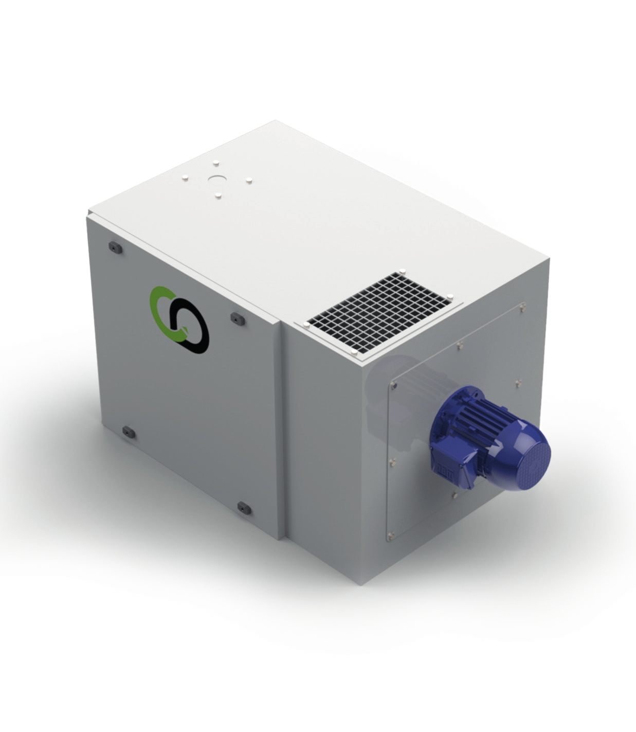
BHS-H
A unit mounted high up, which can be connected directly above a CNC machine to save floor space.
600 – 3 600m³/h
Data sheet BHS-H 
02 / OIL MIST FILTRATION
From a single machining centre to centralised filtration, we adapt capture, ductwork and filtration to your machines and your fluid.
01 / TREAT AT SOURCE
Machining with neat oil or soluble coolant can produce aerosols that spread outside the machines. The solution depends on the number of machines, the space available, the airflow and how condensates are recovered.
Have my network assessedCapture as close as possible to the enclosure or the source.
Condensation and droplet recovery.
Choose the stages according to the pollutant and the target discharge.
02 / THE EQUIPMENT
Two compact units for machine tools and an HE central unit for larger networks.
A unit mounted high up, which can be connected directly above a CNC machine to save floor space.
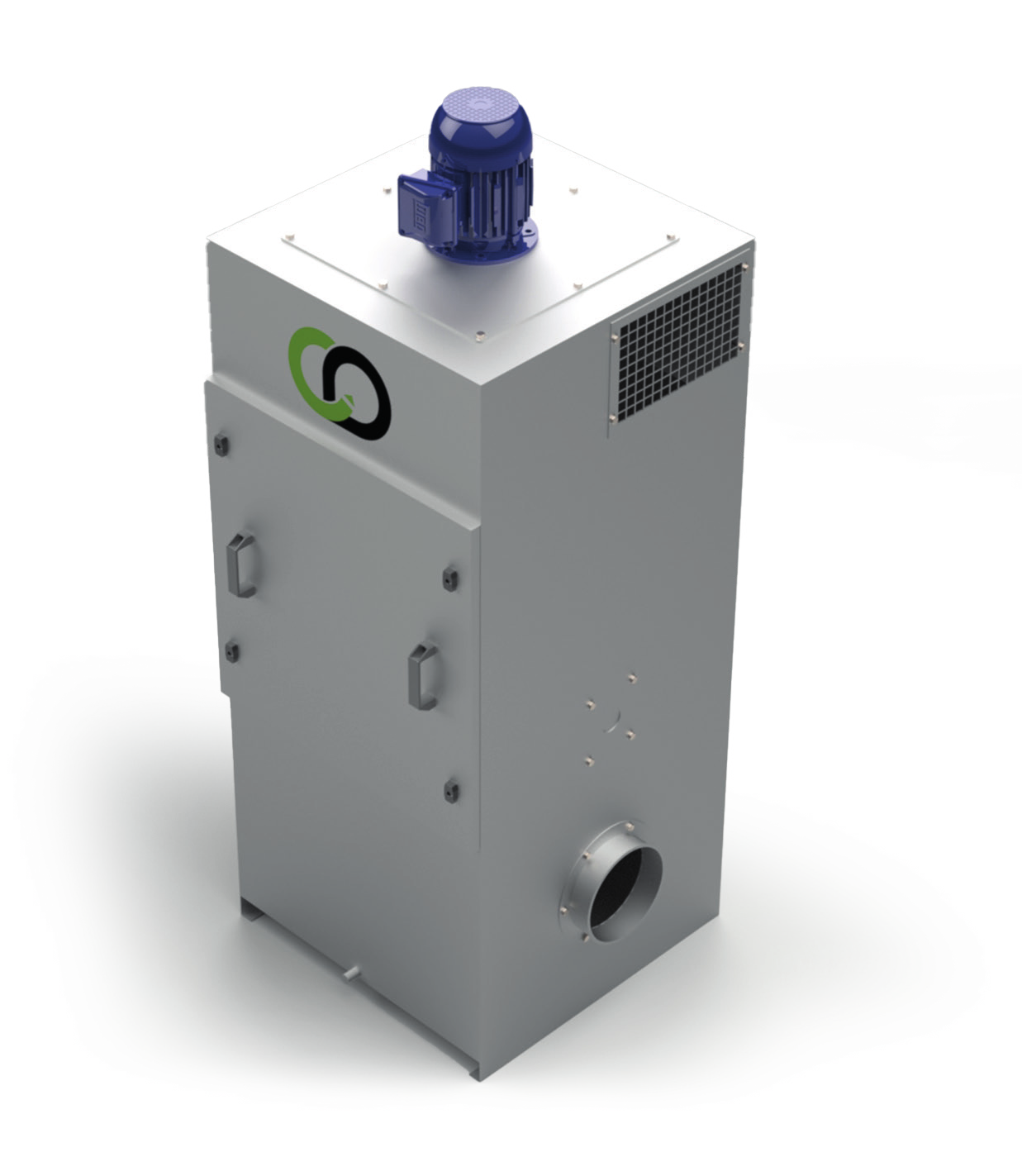
A vertical floor-standing unit, with the option of connecting several CNC machines depending on the network.
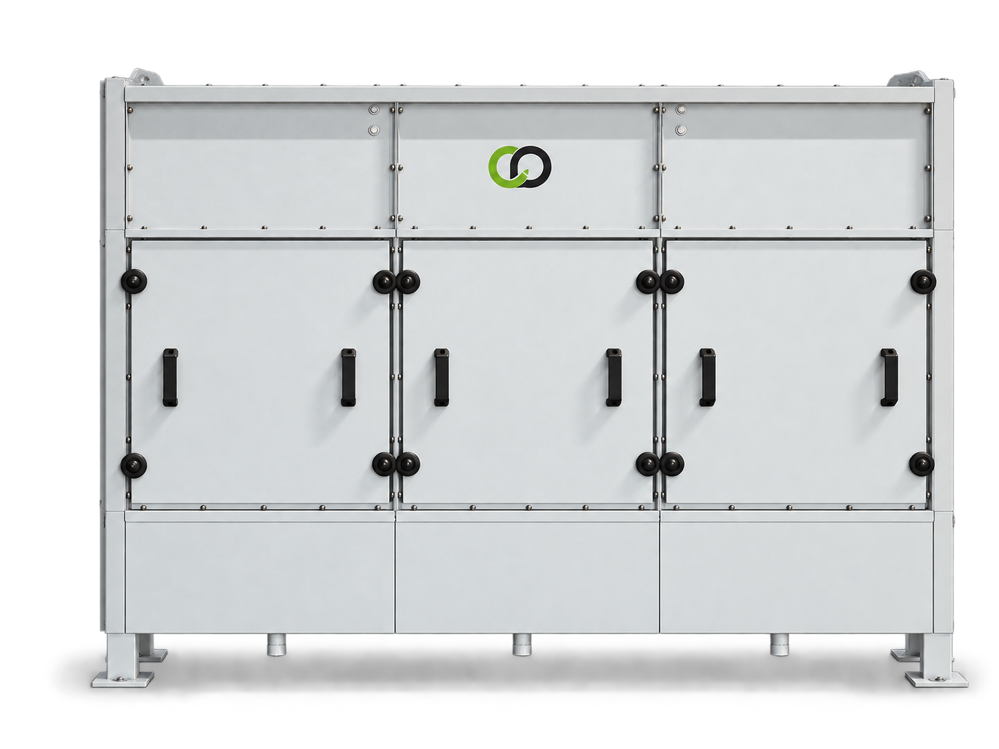
CENTRALISED FILTRATION
To connect several machining stations to a central filtration unit: neat or soluble oil mist, welding fumes and fine particles. EU 3 metal filters, separator and EU 10 final filter, collection tray under the unit. The extraction fan is sized separately according to the ductwork.
03 / COMPARE
The table positions the three ranges. Final sizing takes into account the airflow per machine, pressure losses and the required filtration level.
| Range | Layout | Airflow (table) | Fan | Models |
|---|---|---|---|---|
| BHS-H | High level, above a machine | 600 – 3 600 m³/h | Built into the unit | 500 · 1000 · 2000 · 3500 |
| BHS-V | Vertical floor-standing, several machines can be connected | 600 – 3 600 m³/h | Built into the unit | 100 · 150 · 200 · 250 |
| HE | Central unit on a network | 4 000 – 27 000 m³/h | To be provided separately | HE 5,000 to HE 25,000 |
Indicative airflows taken from the data sheets. HE unit: 99% filtration, 50 mm WG pressure drop (filters 50% clogged). Data subject to change without notice.
04 / YOUR PROCESS
The type of fluid, the number of machines, daily operation and network constraints guide the choice. For centralised extraction, network pressure losses and the fan are studied together with the central unit.
Describe my installationCAPTAIR & DIMAVENT / ENGINEERING OFFICE
Send us the number of machines, the fluids used and your layout constraints. We will study the right solution.